Are
you an enthusiast about trains and locomotives? It’s doesn’t matter whether you
are zealous or not, most of us have to use train as our transportation mode.
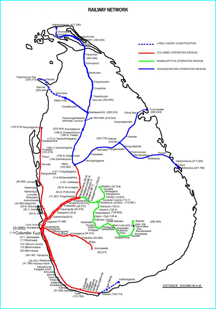
The railway network is spread over considerable terrain in Sri Lanka.
With the
extension of coastal line from Mathara to Beliatta total length railway network
Is close to 1600km now. [1]
Train
locomotives have served as the backbone of railway. Since the inaugural train
dispatched from Colombo to Ambeypussa in 1864 large number of locomotives have
been used to the date. They have been classified into several classes according
to the type of locomotive. But majorly only two types of locomotives can be
categorized with respect to the power source.
1. Steam
locomotives
2. Diesel
locomotives
STEAM LOCOMOTIVES
At
the infant age of Sri Lanka railway (Ceylon Government railway(CGR))
steam locomotives were used. Most of them were imported from the United
Kingdom. Even though Diesel engines were introduced in 1950 steam locomotives
had been the heart of railway until 1970.Over 400 steam locomotives were
imported within that period. They have been categorized under class A, B, C, D,
E, F, J, H, K, L, V and R.
Steam
Engines are external combustion engines where the fluid is separated from the
combustion products. As coal was abundant and cheap fuel in that era, steam
locomotives were highly utilized. But the environmental pollution due to coal
was significantly high. They were subsequently replaced by the diesel
locomotives. As a consequence of this, diesel locomotives were imported to Sri
Lanka after 1940. [2]
DIESEL LOCOMOTIVES
When
consider the diesel locomotives, there are two identifications. They are diesel
locomotive engines and Diesel Multiple Unit(DMU). The uniqueness of DMU is that
it is designed as one unit which train is powered by on-board engines and
engines are incorporated into carriages, wherefore no separate engine is
required.
 |
| Class s12 DMU |
 |
| Class M locomotives |
These diesel locomotives can be categorized in to
three main types according to power transmission method.
1. Diesel
Electrical Locomotives
2. Diesel
Hydraulic Locomotives
3. Diesel
Mechanical Locomotives
Diesel Electrical Locomotives
Majority of diesel locomotives which are currently used
in Sri Lanka are electrical. Class M locomotives and class S DMU after S8 have
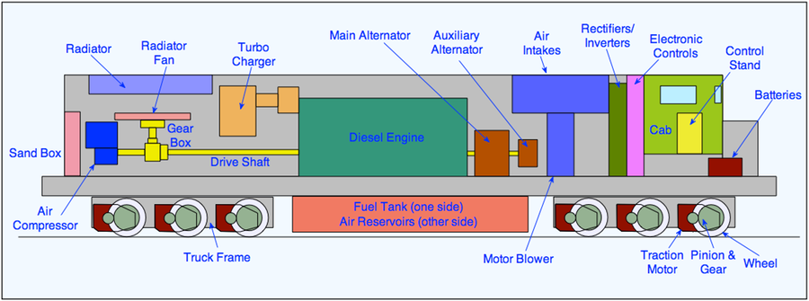
this transmission method. Main parts of this as follows.
 |
| Figure : Parts of Diesel electric Locomotives |
 |
| Figure : Simple chart of parts of Diesel electric locomotives |
v Fuel
tank -Store diesel
v Diesel
engine
v Prime
mover
v Radiator
v Alternator
(those who have DC motors)
v Air
compressor
v rectifier
v Inverter
v Traction
motors
 |
| Figure: A Traction motor |
 |
| Figure : Types of axel |
 |
| Figure : Lighting control system of DMU |
First
the diesel is injected from fuel tank to engine. Diesel engines work by
compressing air. This increases the air temperature inside the cylinder to
such a high degree that atomized diesel fuel injected into the combustion chamber
ignites spontaneously. The crankshaft connected to engine is linked to a
generator or alternator. It converts kinetic energy into electric energy while
generating AC current and it goes through a rectifier, in order to convert AC
current into DC current. The electric locomotives which have DC motors can
directly use converted DC current. But modern locomotives require three phase
AC Current as they consist of some AC motors. Therefore, inverter is required
for that process. The axle of traction motors are connected to axle of the
bogies. Diver can change both direction and speed of locomotive by changing the
current. An air blower is located to cool down the traction motors. It also
helps to cool down the alternator when applying the dynamic brakes to slow down
the train. There are both pros and cons in these models.
v Easy
to maintain
v Low
wearing, tearing
v Less
lubrication
v Smoothness
in transmission
Are the main advantages
v Less
acceleration efficiency than other models
v Power
loss is higher than diesel hydraulic locos.
Are significant
dis-advantages.
DIESEL ELECTRIC LOCOMOTIVES
1) Class
M1
v Built
in Britain
v Imported
in 1952
v Engine
type - mirlees JS12VT
v Power
output-1000hp
v Axel
arrangement-A1A-A1A
v Weight-88tons
v Total
Imported- 25 [3]
2) Class
M2
v Manufactured
in Canada
v Imported -1954-1956
v Sub
classes -M2,M2a,M2b,M2c.M2d
v Power
output -1425hp and 1310hp(M2d)
v Axel
arrangement -A1A and Bo-Bo(M2c)
v Weight
79 tons
v Maximum
speed -112kmph
Total imported -14 (1 was blasted by a bomb, another
one was damaged by tsunami but now repaired and currently 13 in service) [3]
3) Class
M3
v Built
in Sri lanka-1956
v Used
the parts of S1 DMU
v Power output 180hp
v Maximum
speed 89kmph
v Axel
-Bo-Bo
v Weight
-47 tons
v
Total produced -2 [3]
4)Class
M4
v Manufactured
in Canada; imported in 1975
v Engine
type -Alco bombardier 251-c3- 4stroke 12Cylinders
v Power
output 1750 hp
v Maximum
speed-65kmph
v Axel
arrangement -Co-Co
v Total
imported -14 [3]
5)Class
M5
v Built
in Japan
v Built
by Hitachi
v Imported
in 1970
v Sub
classes -M5A ,M5B
v Engine
type -V12 diesel engine
v Power
Output-1640 hp (M5A and M5B-1150hp,M5B-1600 hp)
v Maximum
speed -97kmph
v Axel
arrangement -B0-Bo
v Weight
- 60-70tons
v Total
imported -16 [3]
6)Class
M6
v Built
in Germany
v Imported
in 1979
v Engine
type -V12 two stroke diesel
v Power
output-1650 hp
v Maximum
speed -90kmph
v Axel
arrangement A1A-A1A
v Weight-60-70tons
v Total
imported -16 [3]
7)Class
M7
v Built
in Britain
v Imported
in 1981
v Engine
type -V8 two Strokes
v Power
output-994hp
v Weight
-66tons
v Maximum
speed -80kmph
v Axel
Arrangement -Bo-Bo
v Total
imported- 16 [3]
8)Class
M8
v Built
in India
v Sub
classes -M8A
v Imported
in 1996 and 2001(m8a)
v Engine
type -M8(V16) ,M8A(V12)
v Power
output- 2800hp(M8) ,2200hp(M8A)
v Maximum
speed- 120kmph
v Axel
arrangements -Co-Co
v Weight
-112 tons
v Total
imported -10 [3]
9)Class M9
v Built
in France
v Imported
in 2000
v Engine
type -V12 4 stroke
v Power
output -3200 hp
v Maximum
speed-110kmph
v Axel
arrangement -C0-C0
v Weight
-100 tons
v Total
imported- 10 [3]
10)Class
M10
v Built
in India
v Sub
classes - M10A
v Imported
in 2012
v Engine
type- V12 four strokes
v Power
output -2300hp
v Maximum
speed -120kmph
v Axel
arrangement - Co-Co
v Weight-
117tons
v Total
imported -9 [3]
11)Class M11
v Built
in India
v Imported
in in 2018-19
v Engine
type -EMD 12-710G 3C
v Power
output -3000hp
v Maximum
speed -120kmph
v Axel
arrangement- Co-Co
v Weight
-130tons
v Total
imported -10 [3]
DIESEL ELECTRIC DMUS
1. Class
S9
v Built
in China
v Imported
in 2000.
v Engine
Type -V12
v Power
output -1580hp
v Maximum
speed -100kmph
v Weight
-73 tons
v Axel
Arrangement -B-B
v Total
imported -15sets [3]
2. Class
S10
v Built
in China
v Imported
in 2008
v Engine
type MTU V12 4000R41
v Power
output-1950hp
v Maximum
speed 100kmph
v Axel
arrangement -Bo-Bo
v Weight-
76tons
v Total
imported -15sets [3]
3. Class
S11
v Built
in India
v Imported
in 2011
v Engine
type -KTA50L V16-EFI
v Power
output -1350-1800 hp
v Maximum
speed-110kmph
v Axel
arrangement -Bo-Bo
v Weight-
100tons
v Total
imported-20sets [3]
4. Class
S12
v Built in China
v Imported
in 2012
v Engine
type -MTU V12 4000R1
v Power
output -1950hp
v Maximum
speed-100kmph
v Axel
arrangement -Bo-Bo
v Weight-
76tons
v Total
imported-13sets [3]
5. Class
S13
v Built
in India
v Imported
in 2018-19
v Power
output -1800hp
v Maximum
speed-120kmph
v Axel
arrangement -Bo-Bo
v Weight-
76tons
v Total
imported - 5sets [3]
6.Class S14
v Built
in China
v Imported
in 2019
v Power
output -1950hp
v Maximum
speed-120kmph
v Axel
arrangement -Bo-Bo
v Weight-
74tons
v Total
imported-4sets [3]
7.Class S14a
Imported to carry garbage from Colombo to Aruwakkaru.
DIESEL HYDRAULIC LOCOMOTIVES
There are only few diesel hydraulic locomotives in Sri
Lanka. Class W and Class S1 to S8 DMU locomotives have this type transmission
method.
The main parts are as follows.
v Fuel
tank
v Diesel
engine
v Radiator
v Torque
converter
v Gear
Box.
Usually
RPM value of locomotive engines is lower than car engines. Accordingly, today
the engine RPM varies from 60-100 RPM for large capacity engines to 20,000 RPM
for racing car engines. The power to weight ratio in kg/kW varies from 0.4 to
55 kg/kW for slow speed engines. [4] If typical car
engine gear system is applied, about 10-15 gears are required to operate a
train. Therefore, typical car engines’ gear system is not applicable for
locomotive engines. In order to solve this problem Torque converter is applied
as a unique component. But when the torque is increased speed get decreased. As
a solution, this type of locomotives uses higher RPM than other types and it is
around 1500.Torque converter serves a vital component in the processes of
engine.
As
electric engine, diesel is injected to combustion chamber from fuel tank. During
combustion, drive shaft begins to rotate. This shaft is connected to Gear box
through Torque converter which is a modified fluid coupling system. This fluid
couple consist of two components. [5]
1. An
impeller or a pump connect to the engine and it rotates with the engine.
2. A
turbine connected to the gear box.
These
two consist of two rotors which are placed close to each other and the space
between fans is filled with special oil. When the engine rotates impeller also
get rotated. But it’s not possible to transfer more power in this method
because torque doesn’t rise over certain value and therefore output power is
restricted. But a special component in torque converter which is called “stator”
rectifies this error. stator is located between turbine and impeller ad
main task of it is to change the direction of oil after hitting the turbine. In
this process stator increases the torque while it is keeping stationarity. As a
result the power output is increased. Usually there are two torque converters
in diesel hydraulic locomotives. Then the resultant power is transmitted to
gear box. The throttle of this locomotive has 8 notches. When the driver
changes the notch gearbox work accordingly and rotates the wheel of locomotive
with required power.
 |
| Figure: Control in a locomotive |
The dynamic breaks of these locomotives are also
called as hydrodynamic brakes. The resistive force for the wheels is produced
by the breaking energy heating the hydraulic fluid.
ADVANTAGES
v Higher
acceleration
v Higher
power efficiency
v Less
wheel slips
v Possible
to drive in the flooded conditions
DISADVANTAGES
v Higher
maintain cost
v Wearing
of parts is higher
v Availability
of spare parts is low
Diesel Hydraulic Locomotive Engines
1) Class
W Engines
About
45 of Class w1 engines were imported in 1968 from Germany. And after serving
about 20 years they were retired due to high wearing and less availability of
spare parts.
In 1970 Class w2 Engines were imported and most of
them are out of service now.
A new locomotive was built in Sri Lanka using the
parts of w1 locomotives in 1977.and they were categorized as Class w3. Most of
them are still in service.
 |
| Class w locomotives |
2) DMUs
Class s locomotives up to S8 is categorized in this
group. But now only S8 DMU is in service.
 |
| Class S6 |
 |
| Class S7 |
 |
| Class S5 |
Class
S8
v Built
in Japan (Hitachi +Hyundai (South Kore))
v Imported
in 1989
v Engine
type -MTU V12
v Maximum
Speed -88kmph
v Axel
arrangement - B-B
v Weight
-70 tons
v Total
imported -20 sets
DIESEL MECHANICAL LOCOMOTIVES
This
transmission system is not used for high power locomotives. This transmission
is used for small engines such as shunting locomotives. The main reason for them
not being used in heavy locomotives is if the power supplied from the engine is
directly connected to gear box, both engine and gear box can be severely
damaged due to the large inertial force. Like other transmission methods, fuel
combustion in chamber powers the shaft connected to gear box. This is done
through a fluid coupling method which act as a hydraulic clutch. Then the
mechanical energy output from the gear box is used to rotate the wheels. The
power transmitted is quite smaller than other locomotives as they are in the
range of 300 to 500 horsepower while on other locomotives it is in the range of
1000-3000.
 |
| A shunter (class G and Y) |
FUTURE OF SRI LANKA RAILWAY AND
LOCOMOTIVES
After
initiating the railway service in 1864, gradually it has passed several
milestones on the way. But we are still quite behind in railway technology and
facilities compared to many developed countries. As young blooming engineers
our prime task is to develop these technologies and facilities in order to make
these transportation modes more upgraded. [6]
S.G.S.S DE JAYATHUNGA
UNIVERTSITY OF SRI JAYAWARDENAPURA
DEPARTMENT OF CIVIL ENGINEERING
References
[1]
|
|
[2]
|
|
[3]
|
SLRF Staff, "Class M2 - Sri Lanka
Railway Forum," 22 September 2019. [Online]. Available:
https://slrailwayforum.com. [Accessed 12 April 2020].
|
[4]
|
S. D. Mane, "Technologies adopted
in Diesel Locomotive Engines over Indian Railways," January 2016.
[Online]. Available: https://www.researchgate.net. [Accessed 17 April
2020].
|
[5]
|
|
[6]
|
S. A. Jayasekera, "Megapolis
Development Ministry's Light Railway System JICA to provide US$ 1.7
billion," Mirror Citizen, vol. 7, no. 3, p. 573, 2018.
|